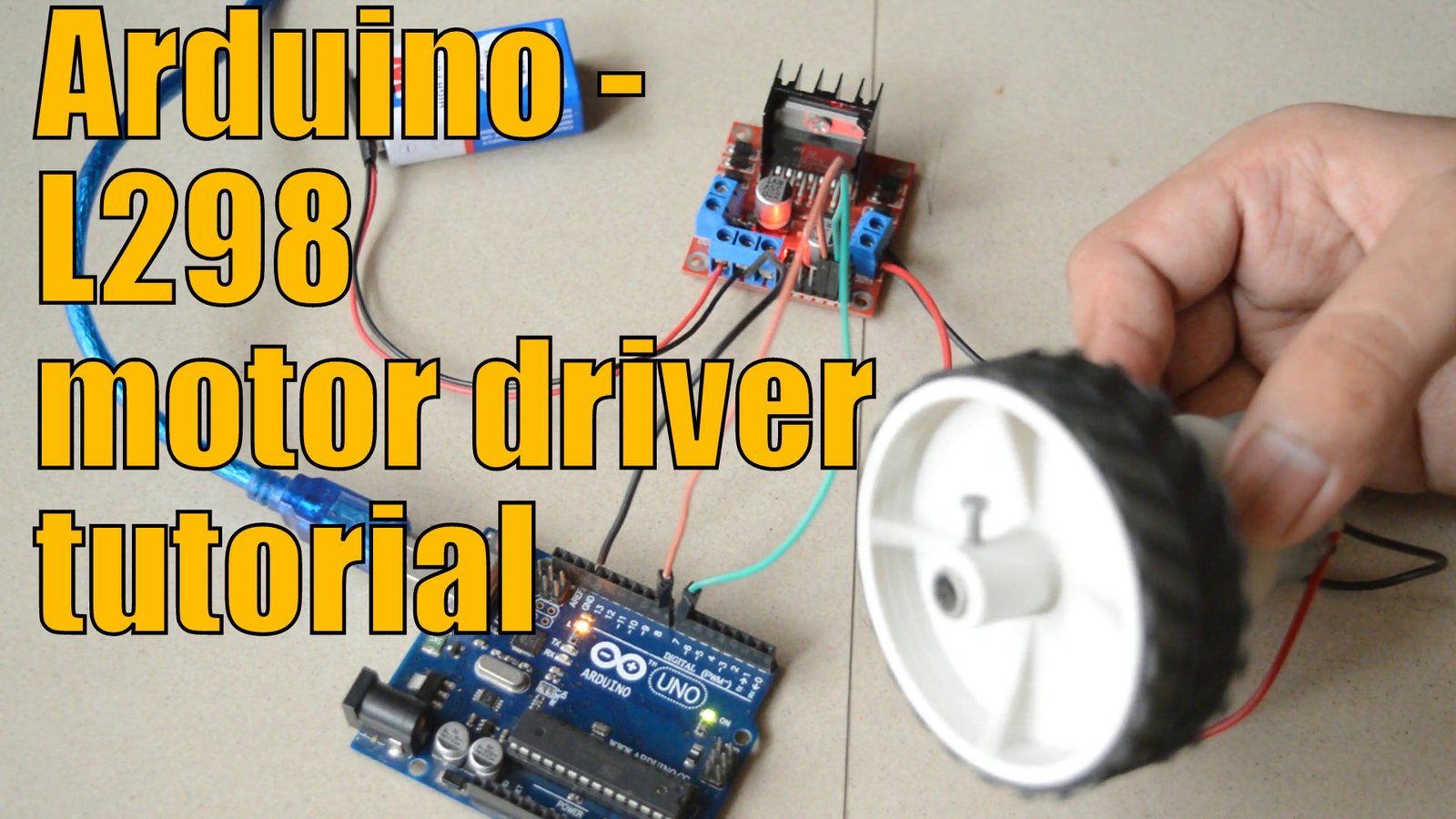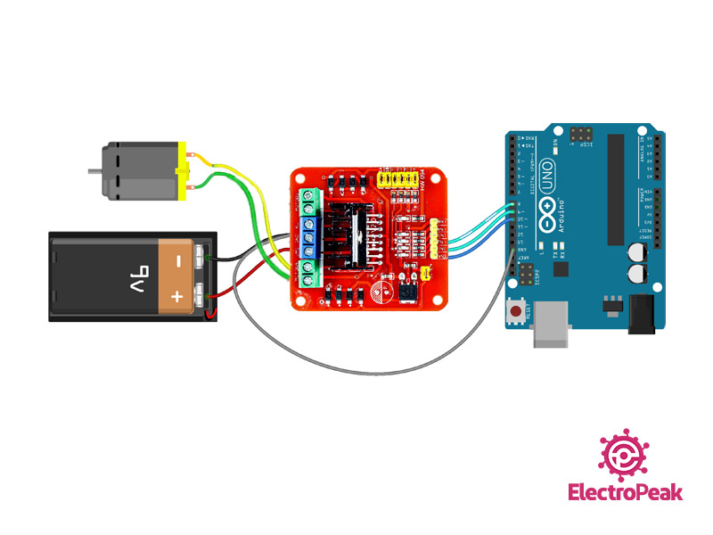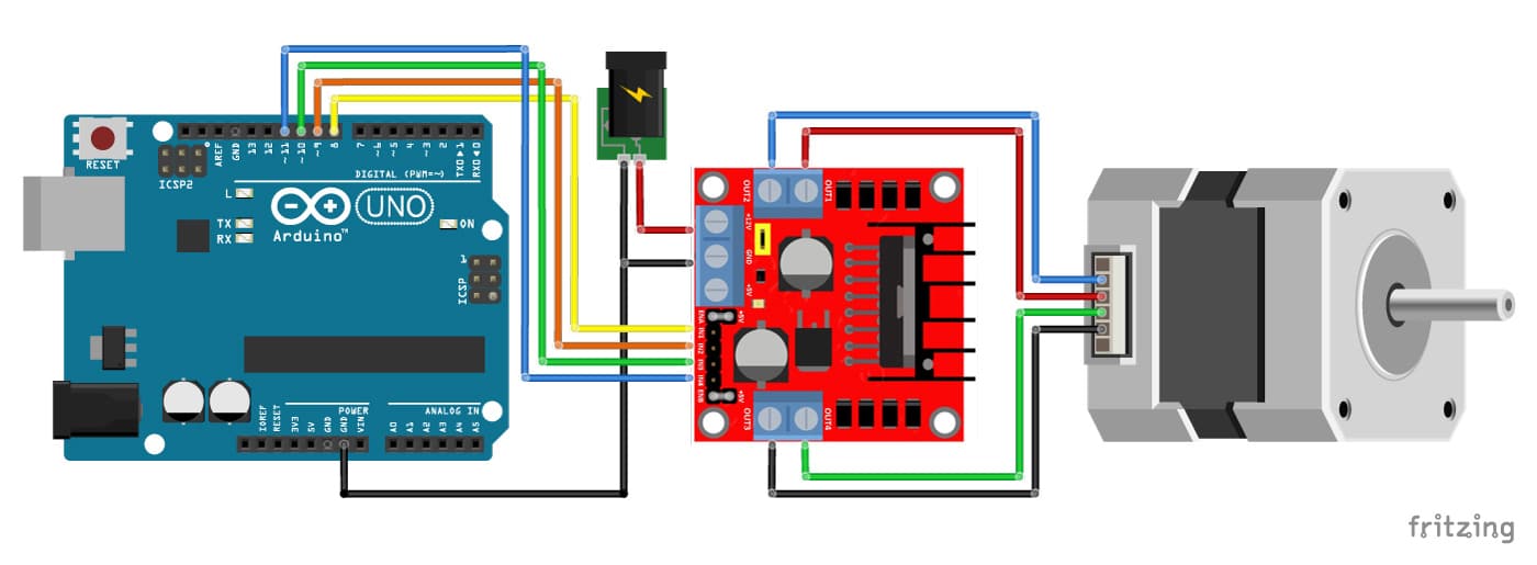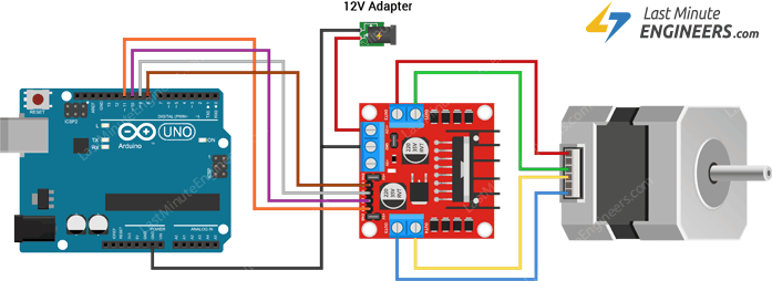

Wiring and controlling a DC motor is quite easy, you just need to connect each motor to A1-A2, B3-B4 or Out 1-2, Out 3-4 It depends how the L298n board configuration. If you want to build your own, see the schematic diagram below. There are many model of l298n boards in the market, see the photo below for examples.

It is excellent for robotics applications and well fit to a microcontroller. This module has ease to connect and drive a dc motor or stepper motor allows you to easily and intently control two motor up to 2A each in both direction or one stepper motor. Additional supply input is provided so that the logic works at lower voltage. The emitters of the lower transistors of each bridge are connected together and the corresponding external terminal can be use for the connection of external sensing resistor. Two enabled inputs are provided to enable or disable the device independently of the input signals. It is a high voltage and high current full dual bridge driver designed to accept standard TTL logic level and drive inductive loads such as relays, solenoids and DC stepper motor. The l298 is an integrated monolithic circuit in a 15 lead multi-watt and power S020 package.


So the code lights up the L298N for 2 seconds as expected but it the motor doesnt run.The L298 H Bridge is base on l298 Chip manufacture by ST Semiconductor. I need my voltmeter.btw its getting 4.85V at the L298N 12V+ and GND terminals. I have it working such that the L298N gets power when the fet activates it via D5 and a 1k Resistor, but for some reason the motor doesn't run. Ok Im using an FQP which Ive used before at logic levels to control the motor.


 0 kommentar(er)
